| KIT #: | ? |
| PRICE: | @$25.00 long ago |
| DECALS: | One option |
| REVIEWER: | Joel Hamm |
| NOTES: | Limited run kit. Long OOP |
| HISTORY |
Inventions may be mothered by necessity, but they are frequently fathered by desperation. The urge to atone for twenty years of pre-WWII snoozing forced a nascent military-industrial complex to consider no design too radical, nor scheme too hair-brained, to at least have a look at. Some were auspicious enough to warrant all-out effort; so radar, sonar, and of course nuclear fission played pivotal roles. Some displayed promise, but demanded unaffordable diversion of technical resources; meaning jet planes had to be deferred until the next war. Others simply seemed to be too much trouble, or failed expectations, or approached fruition just as swords were being re-beaten into refrigerators.
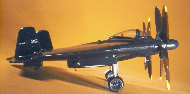
Falling, for all three reasons, into Category Number 3 was the flying saucer. No, not the flying saucer that crashed at Roswell, spewing decades of dead aliens across the tabloids; but a terrestrially conceived and powered aircraft, extraordinary for its all-wing configuration; or rather all circular lifting surface. The craft was designed and patented in 1938 by NACA engineer Charles Zimmerman. The Vought Company scooped him on board to develop the idea after the Navy started salivating over astounding performance possibilities. Wind tunnel studies suggested an extreme machine able to takeoff and land vertically, hover, out - climb an angel, and dash from 20 to 550 MPH.
A full scale wood and fabric test version, dubbed the V-173, accumulated 130+ hours of air time that gave credence to these extravagant estimates, but hinted at insuperable technical difficulties. It wasn’t until the late forties that a prototype was built. It got no farther than taxi tests when, in 1948, the project was canceled. Torch and wrecking ball accomplished an inexplicable proviso that the machine be destroyed. (The yellow V-173 reportedly survives in storage awaiting display at D.C.’s National Air and Space Museum) Controversy swirls over whether the “flying pancake” ever flew. Some accounts claim it actually lifted off during taxi trials; others insist that it remained earthbound. That is the main, but hardly the only point on which references refute each other . One source asserts that it was powered by prone radial engines through a complex of geared shafts. Another alleges the unlikely installation of gas turbines. Configuration and history remain a function of which photos, diagrams, or narratives are being relied upon. For bookwork, try U.S. Naval Fighters 1922 to 1980’s by Lloyd S. Jones, and United States Navy mid Marine Corps Fighters 1918-1962 by Paul R. Mall.
| THE KIT |
As an aircraft that literally and
figuratively went nowhere, the flapjack demands classification as a flop;
but as a model it makes a fetching prospect. A subject of such limited
appeal wouldn’t light fires under Revell or Hasegawa (*), but it offers
meat and potatoes with gobs of wavy to the cottage industry kit makers.
These one-man-show operators appear and van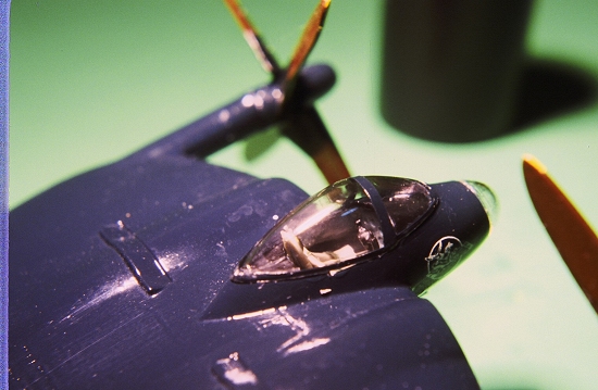 ish with the frequency of
cabinet-level political appointees, but manage nevertheless to research,
tool, mold, package, and distribute a fascinating array of injection molded
plastic or “multimedia” kits. Initial offerings were crude; but quality is
steadily advancing; though a lack of sophistication still restricts their
suitability to experienced, or at least emotionally stable hobbyists. The
British Pegasus Company was one of the first on the scene. Their limited
editions of only a few hundred of each kit were snapped up, but often left
un-built; so this 1/72 scale version of Vought’s XF5U-1 may still be found
at swap sales or internet trades.
ish with the frequency of
cabinet-level political appointees, but manage nevertheless to research,
tool, mold, package, and distribute a fascinating array of injection molded
plastic or “multimedia” kits. Initial offerings were crude; but quality is
steadily advancing; though a lack of sophistication still restricts their
suitability to experienced, or at least emotionally stable hobbyists. The
British Pegasus Company was one of the first on the scene. Their limited
editions of only a few hundred of each kit were snapped up, but often left
un-built; so this 1/72 scale version of Vought’s XF5U-1 may still be found
at swap sales or internet trades.
Pegasus’s problems typify expectations on opening one of these plastic bag productions: thick and uneven injection, mismatched mold halves, flash infestation, lack of locating holes and mounting pins, and small parts needing to be scratch built. Surfaces suffer from small holes and sand-like granules. A soft and grainy plastic probably facilitates the injection process, but causes headaches for builders. It sands poorly; crumbling, clogging the abrasives, and melting from friction. That difficulty is solved by doing all sanding under running water. Nor does this brand of styrene take kindly to fillers. It is softer and ablates more easily than most putties, frustrating attempts at a smoothly feathered transition. “Bondo” and “Green Stuff” can be used for major voids, but for topcoats and small depressions use multiple layers of automotive spot-filling primer, such as “Plasticote”.
| CONSTRUCTION |
As with vacu-formed models, all mating
surfaces must be machined level by sanding on a glass pane or equally flat
surface. The upper and lower fuselage halves are molded in halves again,
creating an uneven and unsightly seam line, The temptation presents itself
to reinforce the joint with styrene strips, but don’t. Differential
shrinkage when the glue dries will cause the clamshell pieces to bow. They
are best joined while clam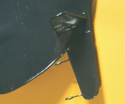 ped or taped to the glass sheet. Before fuselage
closure, the “turbine bullets” must be installed in the intake tunnels.
Available photos show that the bullet nose should be somewhat sharper but
that error is hardly worth tinkering with. No locating lines or ridges are
provided, but it appears that the bullet tip should sit tangent with the
extended leading edge line. The thickness of the nacelle walls has to first
be reduced. A ball shaped burr in a rototool does a nice job. Reinforcing
gussets of sheet styrene should also be fixed behind the turbine wheels to
prevent their being squashed out of place when the clamshell halves come
together. It is advisable also before that happens, to skip ahead a few
steps and drill locating depressions, or glue in hollow stubs, to hold the
landing gear struts.
ped or taped to the glass sheet. Before fuselage
closure, the “turbine bullets” must be installed in the intake tunnels.
Available photos show that the bullet nose should be somewhat sharper but
that error is hardly worth tinkering with. No locating lines or ridges are
provided, but it appears that the bullet tip should sit tangent with the
extended leading edge line. The thickness of the nacelle walls has to first
be reduced. A ball shaped burr in a rototool does a nice job. Reinforcing
gussets of sheet styrene should also be fixed behind the turbine wheels to
prevent their being squashed out of place when the clamshell halves come
together. It is advisable also before that happens, to skip ahead a few
steps and drill locating depressions, or glue in hollow stubs, to hold the
landing gear struts.
After filling, filing, cleaning up all joints, and re-scribing lost panel lines, the horizontal and vertical fins must be affixed. There are no locating marks for the latter so check the plan view drawing. To overcome the lack of tabs and slots, make a quick grab glue joint by first priming both parts with solvent, such as Plastruct, then applying a bead of semi-gel such as Testors Liquid Cement. Wheel well doors are molded as closed units. Attach them temporarily prior to painting (after spraying the interior gray) The star-and-bar decal covers the right door, and applying it to the split halves would be difficult. The “pickiness” of the surface texture responds well to scrubbing with a cosmetic facial buffer - a sort of soft “Scotchbrite” pad. A follow-up with “Soft-Scrub” cleanser removes the gloss and improves paint “bite”. A trial spraying of sandable primer on the under-belly created a smooth texture, but obscured scribing and detail; so it was omitted top-side.
| COLORS & MARKINGS |
Glossy Dark Sea Blue is the proper shade. Testors Model Master makes it and even quotes the correct federal stock number. After decaling, I departed from my standard ritual of “Future” floor wax overcoat, experimenting instead with what is called water based polyurethane, but is in fact another form of acrylic finish. This stuff goes on thinner than Future, meaning it is more forgiving of an improper viscosity/air pressure match; but also requires many more coats for an equal gloss. It might be a good choice over metallic finishes.
| FINAL CONSTRUCTION |
While the main assembly dried, details
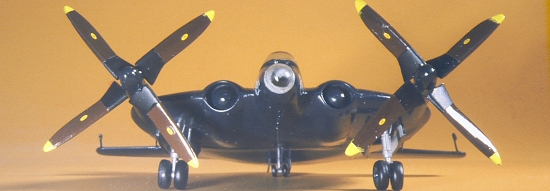
and appendages could be attended to. The paddle bladed props are built up
from, separate blades and hubs, noting that they are left and right handed
and counter-rotate outward at the top. The propellers were unusual (wasn’t
everything?) in having the pairs of opposing blades attached to the hub in
staggered vertical planes. Available photos show that the distance was much
closer than the molded-in attach points represent. Gluing the blades at the
indicated holes produced a bizarre propeller, so the blades were plucked
out and re-inserted in nearly the same plane, resulting in a closer
semblance to available photos. The undercarriage struts provided in the kit
are cast from white metal. In trying to clean up the graininess, they
broke, so I ended up scratch building a new set from bits of plastic rod,
 tube, and sprue. They were built as units with oleos, side braces and
retraction arms attached to base plates, so the whole assemblage could be
dropped into the wheel well and quick-epoxied in place. A feature omitted
in the kit drawings, but clearly evident in photos and other diagrams is
the four curved balance arms protruding from the horizontal this, These
were fabricated from stretched sprue with tear-drop balance horn tips
actually found in the spare parts box. Getting them all hung at the right
length and angle took a fair amount of fussing mid cussing. The ventral
antenna mast, wire, and pitot arm also had to be scrounged from the
leftovers bin. An instrument panel is provided (glue it in before fuselage
closure) but the kit-supplied ejection seat seemed lost rattling around in
the cockpit void. I made a more properly sized seat and headrest, added
seat belts cut from tape, and threw in a control yoke; though the real
plane may have used a joystick. (How many people out there know that it is
really a “Joyce stick” - so named for its inventor?).
tube, and sprue. They were built as units with oleos, side braces and
retraction arms attached to base plates, so the whole assemblage could be
dropped into the wheel well and quick-epoxied in place. A feature omitted
in the kit drawings, but clearly evident in photos and other diagrams is
the four curved balance arms protruding from the horizontal this, These
were fabricated from stretched sprue with tear-drop balance horn tips
actually found in the spare parts box. Getting them all hung at the right
length and angle took a fair amount of fussing mid cussing. The ventral
antenna mast, wire, and pitot arm also had to be scrounged from the
leftovers bin. An instrument panel is provided (glue it in before fuselage
closure) but the kit-supplied ejection seat seemed lost rattling around in
the cockpit void. I made a more properly sized seat and headrest, added
seat belts cut from tape, and threw in a control yoke; though the real
plane may have used a joystick. (How many people out there know that it is
really a “Joyce stick” - so named for its inventor?).
Many cottage kits use vacu-formed clear parts, but Pegasus molds its transparencies the old-fashioned way - causing cataraceous optical quality. After sanding through graded abrasives, burnishing with “Flitz” polish, and a coating of “Future”, the canopy and nose bowl were clear enough to stick on with white glue.
| CONCLUSIONS |
Perched on the “oddities” shelf alongside Northrop’s XB-35, the Curtiss XP-55 Ascender (Ass-Ender), and other erstwhile ne’er-do-well’s, Pegasus’ Vought XF5U posited an intriguing point, Flying wings, canards, VTOL, and other anomalies were excellent ideas ahead of their time, foiled in their potential until required technologies caught up. Perhaps some enterprising aircraft company will now have another look at those 1938 performance promises, apply modem materials, engines, and computer controls, and create a flapjack that finally flies.
(*) I may be wrong about that. After this review was written (several years ago) the Squadron Shop catalog listed a Hasegawa XF5U in 1/72 scale. That listing quickly vanished from subsequent issues; and nobody has ever reported seeing, let alone building the kit. It may have been half-hearted foray by the Japanese into re-packaging and marketing these British short run productions (this very kit), a typographical error, or, most likely, a delusional experience of the catalog compiler brought on by over exposure to airplane glue fumes. Anyone with information clarifying the mystery is welcome to respond.
Your editor would like to direct the reader to the Kit Review Archives where your editor built the Hasegawa kit several years ago.
March 2005
If you would like your product reviewed fairly and quickly by a site that has about 300,000 visitors a month, please contact me or see other details in the Note to Contributors.